
I’m going to show you how to turn on your funk motor get started with MicroPython on an Espressif ESP32 development board. In this first part of this tutorial, I’ll show you how to:
- Get up & running with MicroPython on the ESP32
- Connect to WiFi
- Upload scripts to the board
- Read the ambient temperature (everyone loves that, right?)
In the forthcoming second part of this tutorial, I’ll show you publish the data you’ve collected with MQTT.
This guide expects you to possess:
- …familiarity with the command-line
- …basic experience interfacing with development boards (like Arduino)
- …a basic understanding of programming in Python
If I’ve glossed over something I shouldn’t have, please let me know!
Before we begin, you will need some stuff.
Bill of Stuff
You need Stuff in the following categories.
Hardware

Not necessarily this stuff, but same idea. Photo by Alexandra Cárdenas
- One (1) ESP32 development board such as the SparkFun ESP32 Thing (any kind will do; they are all roughly the same)
- One (1) DS18B20 digital thermometer (datasheet) in its TO-92 package
- One (1) 4.7kꭥ resistor
- Four (4) jumper wires
- One (1) 400-point or larger breadboard
- One (1) USB Micro-B cable
If you need to solder header pins on your dev board: do so.
If you have a DS18B20 “breakout board”: these typically have the resistor built-in, so you won’t need it. You will need to figure out which pin is which, however.
Software
You will need to download and install some software. Some of these things you may have installed already. Other things may need to be upgraded. This guide assumes you ain’t got jack squat.
I apologize that I don't have much information for Windows users! However, I assure you that none of this is impossible.
VCP Driver
If you're running macOS or Windows, you may need to download and install a Virtual COM Port (VCP) driver, if you haven't done so already. Typically, the USB-to-serial chip on these boards is a CP210x or FT232RL; check the datasheet for your specific board or just squint at the IC near the USB port.
Newer Linux kernels have support for these chips baked-in, so driver installation is unnecessary.
Here's an example of a CP2104 on an ESP32 dev board of mine:
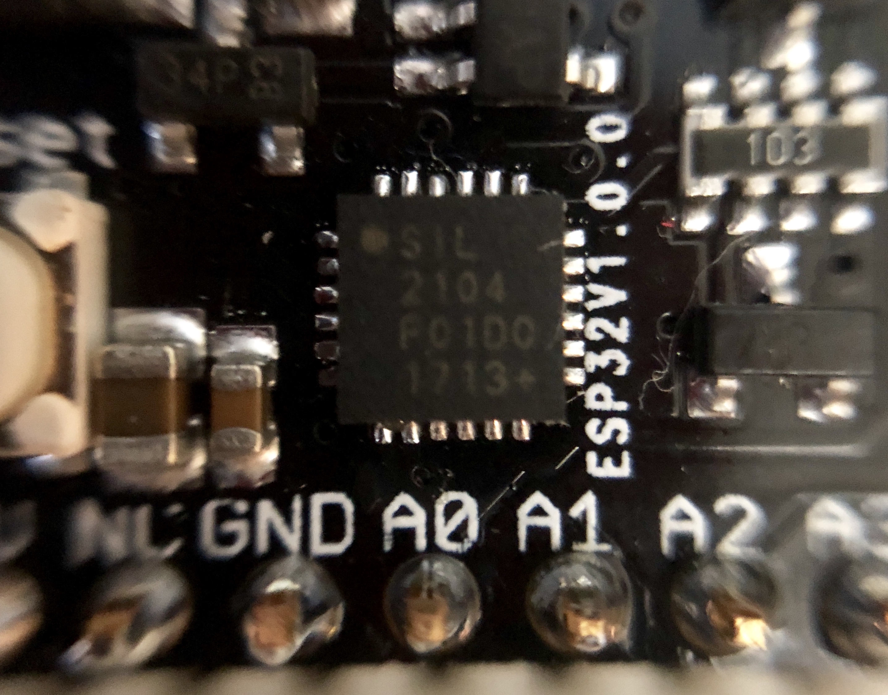 A SiLabs CP2104. Thanks, macro lens!
To assert the driver is working, plug your dev board into your computer. If you’re on Linux, check for /dev/ttyUSB0:
$ ls -l /dev/ttyUSB0
crw-rw---- 1 root dialout 188, 0 Dec 19 17:04 /dev/ttyUSB0
Or /dev/tty.SLAB_USBtoUART on macOS:
$ ls -l /dev/tty.SLAB_USBtoUART
crw-rw-rw-  1 root  wheel   21,  20 Dec 19 17:10 /dev/tty.SLAB_USBtoUART
Serial Terminal
A free, cross-platform, GUI terminal is CoolTerm. Linux & macOS users can get away with using screen on the command line. More purpose-built solutions include miniterm, which ships with Python 3, and can be launched via python3 -m serial.tools.miniterm, and minicom.
Python, Etc.
You will also need:
- Python v3.6.x
- For extra libraries, a clone or archive of micropython/micropython-lib (
git clone https://github.com/micropython/micropython-lib)
How you install these will vary per your installation of Python:
- To flash the board, esptool (version 2.2 or newer)
- To manage files on the board, adafruit-ampy
You could try pip3 install esptool adafruit-ampy. This worked for me on macOS with Homebrew; YMMV. You might need to preface that with sudo if not using Homebrew.
MicroPython Firmware
Finally, you’ll need to download the latest MicroPython firmware for ESP32.
Now that our tools are at hand, we can begin by flashing the ESP32 board with MicroPython.
Flashing MicroPython & First Steps
Unless MicroPython is already installed on your ESP32, you will want to start by connecting it to your computer via USB, and erasing its flash:
In the below examples, replace
/dev/tty.SLAB_USBtoUARTwith the appropriate device or COM port for your system.
$ esptool.py --chip esp32 -p /dev/tty.SLAB_USBtoUART erase_flash
esptool.py v2.2
Connecting........___
Chip is ESP32D0WDQ6 (revision 1)
Uploading stub...
Running stub...
Stub running...
Erasing flash (this may take a while)...
Chip erase completed successfully in 4.6s
Hard resetting...
Now, we can flash it with the firmware we downloaded earlier:
$ esptool.py --chip esp32 -p /dev/tty.SLAB_USBtoUART write_flash \
  -z 0x1000 ~/Downloads/esp32-20171219-v1.9.2-445-g84035f0f.bin
esptool.py v2.2
Connecting........_
Chip is ESP32D0WDQ6 (revision 1)
Uploading stub...
Running stub...
Stub running...
Configuring flash size...
Auto-detected Flash size: 4MB
Compressed 936288 bytes to 587495...
Wrote 936288 bytes (587495 compressed) at 0x00001000 in 51.7 seconds (effective 144.8 kbit/s)...
Hash of data verified.

Leaving...
Hard resetting...
If you’re feeling dangerous, you can increase the baud rate when flashing by using the
--baudoption.
If that worked, you should be able to enter a MicroPython REPL by opening up the port:
# 115200 is the baud rate at which the REPL communicates
$ screen /dev/tty.SLAB_USBtoUART 115200

>>>
Congratulations, >>> is your REPL prompt. This works similarly to a normal Python REPL (e.g. just running python3 with no arguments). Try the help() function:
>>> help()
Welcome to MicroPython on the ESP32!

For generic online docs please visit http://docs.micropython.org/

For access to the hardware use the 'machine' module:

import machine
pin12 = machine.Pin(12, machine.Pin.OUT)
pin12.value(1)
pin13 = machine.Pin(13, machine.Pin.IN, machine.Pin.PULL_UP)
print(pin13.value())
i2c = machine.I2C(scl=machine.Pin(21), sda=machine.Pin(22))
i2c.scan()
i2c.writeto(addr, b'1234')
i2c.readfrom(addr, 4)

Basic WiFi configuration:

import network
sta_if = network.WLAN(network.STA_IF); sta_if.active(True)
sta_if.scan()                             # Scan for available access points
sta_if.connect("<AP_name>", "<password>") # Connect to an AP
sta_if.isconnected()                      # Check for successful connection

Control commands:
  CTRL-A        -- on a blank line, enter raw REPL mode
  CTRL-B        -- on a blank line, enter normal REPL mode
  CTRL-C        -- interrupt a running program
  CTRL-D        -- on a blank line, do a soft reset of the board
  CTRL-E        -- on a blank line, enter paste mode

For further help on a specific object, type help(obj)
For a list of available modules, type help('modules')
If you’ve never seen this before on an MCU: I know, crazy, right?
You can type in the commands from “Basic WiFi configuration” to connect. You will see a good deal of debugging information from the ESP32 (this can be suppressed, as you’ll see):
>>> import network
>>> sta_if = network.WLAN(network.STA_IF)
I (323563) wifi: wifi firmware version: 111e74d
I (323563) wifi: config NVS flash: enabled
I (323563) wifi: config nano formating: disabled
I (323563) system_api: Base MAC address is not set, read default base MAC address from BLK0 of EFUSE
I (323573) system_api: Base MAC address is not set, read default base MAC address from BLK0 of EFUSE
I (323593) wifi: Init dynamic tx buffer num: 32
I (323593) wifi: Init data frame dynamic rx buffer num: 64
I (323593) wifi: Init management frame dynamic rx buffer num: 64
I (323603) wifi: wifi driver task: 3ffe1584, prio:23, stack:4096
I (323603) wifi: Init static rx buffer num: 10
I (323613) wifi: Init dynamic rx buffer num: 0
I (323613) wifi: Init rx ampdu len mblock:7
I (323623) wifi: Init lldesc rx ampdu entry mblock:4
I (323623) wifi: wifi power manager task: 0x3ffe84b0 prio: 21 stack: 2560
W (323633) phy_init: failed to load RF calibration data (0x1102), falling back to full calibration
I (323793) phy: phy_version: 362.0, 61e8d92, Sep  8 2017, 18:48:11, 0, 2
I (323803) wifi: mode : null
>>> sta_if.active(True)
I (328553) wifi: mode : sta (30:ae:a4:27:d4:88)
I (328553) wifi: STA_START
True
>>> sta_if.scan()
I (389423) network: event 1
[(b'SON OF ZOLTAR', b"`\xe3'\xcf\xf4\xf5", 1, -57, 4, False), (b'CenturyLink6105', b'`1\x97%\xd9t', 1, -96, 4, False)]
>>> sta_if.connect('SON OF ZOLTAR', '<REDACTED>')
>>> I (689573) wifi: n:1 0, o:1 0, ap:255 255, sta:1 0, prof:1
I (690133) wifi: state: init -> auth (b0)
I (690133) wifi: state: auth -> assoc (0)
I (690143) wifi: state: assoc -> run (10)
I (690163) wifi: connected with SON OF ZOLTAR, channel 1
I (690173) network: event 4
I (691723) event: sta ip: 10.0.0.26, mask: 255.255.255.0, gw: 10.0.0.1
I (691723) network: GOT_IP
I (693143) wifi: pm start, type:0

>>> sta_if.isconnected()
True
Cool, huh?
Now that we know we can connect to WiFi, let’s have the board connect every time it powers up.
Creating a MicroPython Module
To perform tasks upon boot, MicroPython wants you to put code in a file named boot.py, which is a MicroPython module.
Let’s create boot.py with code modified from the MicroPython ESP8266 docs, replacing where indicated:
def connect():
    import network
    sta_if = network.WLAN(network.STA_IF)
    if not sta_if.isconnected():
        print('connecting to network...')
        sta_if.active(True)
        sta_if.connect('<YOUR WIFI SSID>', '<YOUR WIFI PASS>')
        while not sta_if.isconnected():
            pass
    print('network config:', sta_if.ifconfig())
We can also create a function to disable debugging output. Append to boot.py:
def no_debug():
    import esp
    # this can be run from the REPL as well
    esp.osdebug(None)
These functions will be defined at boot, but not called automatically. Let’s test them before making them automatically execute.
To do this, we can upload boot.py. You’ll need to close the connection to the serial port. If you’re using screen, type Ctrl-A Ctrl-\, then y to confirm; otherwise disconnect or just quit your terminal program.
Uploading a MicroPython Module
Though there are other ways to do this, I’ve found the most straightforward for the ESP32 is to use ampy, a general-purpose tool by Adafruit. Here’s what it can do:
$ ampy --help

Usage: ampy [OPTIONS] COMMAND [ARGS]...

  ampy - Adafruit MicroPython Tool

  Ampy is a tool to control MicroPython boards over a serial
  connection.  Using ampy you can manipulate files on the board's
  internal filesystem and even run scripts.

Options:
  -p, --port PORT  Name of serial port for connected board.  Can
                   optionally specify with AMPY_PORT environemnt
                   variable.  [required]
  -b, --baud BAUD  Baud rate for the serial connection (default
                   115200).  Can optionally specify with AMPY_BAUD
                   environment variable.
  --version        Show the version and exit.
  --help           Show this message and exit.

Commands:
  get    Retrieve a file from the board.
  ls     List contents of a directory on the board.
  mkdir  Create a directory on the board.
  put    Put a file or folder and its contents on the...
  reset  Perform soft reset/reboot of the board.
  rm     Remove a file from the board.
  rmdir  Forcefully remove a folder and all its...
  run    Run a script and print its output.
MicroPython stores files (scripts or anything else that fits) in a very basic filesystem. By default, an empty boot.py should exist already. To list the files on your board, execute:
$ ampy -p /dev/tty.SLAB_USBtoUART ls
boot.py
Using the get command will echo a file’s contents to your shell (which could be piped to a file, if you wish):
$ ampy -p /dev/tty.SLAB_USBtoUART get boot.py
# This file is executed on every boot (including wake-boot from deepsleep)
We can overwrite it with our own boot.py:
$ ampy -p /dev/tty.SLAB_USBtoUART put boot.py
And retrieve it to see that it overwrote the default boot.py:
$ ampy -p /dev/tty.SLAB_USBtoUART get boot.py
def connect():
    import network
    sta_if = network.WLAN(network.STA_IF)
    if not sta_if.isconnected():
        print('connecting to network...')
        sta_if.active(True)
        sta_if.connect('<YOUR WIFI SSID>', '<YOUR WIFI PASS>')
        while not sta_if.isconnected():
            pass
    print('network config:', sta_if.ifconfig())

def no_debug():
    import esp
    # this can be run from the REPL as well
    esp.osdebug(None)
Success! This is the gist of uploading files with ampy. You can also upload entire folders, as we’ll see later.
From here, we can open our REPL again, and run our code. No need to restart the board!
Running a MicroPython Module
In following examples, I will eliminate the command prompt (>>>) from code run in a REPL, for ease of copying & pasting.
Re-connect to the REPL.
$ screen /dev/tty.SLAB_USBtoUART 115200
First, we’ll disconnect from WiFi:
import network
sta_if = network.WLAN(network.STA_IF)
sta_if.disconnect()
Debug output follows:
I (3299583) wifi: state: run -> init (0)
I (3299583) wifi: n:1 0, o:1 0, ap:255 255, sta:1 0, prof:1
I (3299583) wifi: pm stop, total sleep time: 0/-1688526567
I (3299583) wifi: STA_DISCONNECTED, reason:8
Then, we can import the boot module. This will make our connect and no_debug functions available.
import boot
connect()
Output:
connecting to network...
I (87841) wifi: n:1 0, o:1 0, ap:255 255, sta:1 0, prof:1
I (88401) wifi: state: init -> auth (b0)
I (88401) wifi: state: auth -> assoc (0)
I (88411) wifi: state: assoc -> run (10)
I (88441) wifi: connected with SON OF ZOLTAR, channel 1
I (88441) network: event 4
I (90081) event: sta ip: 10.0.0.26, mask: 255.255.255.0, gw: 10.0.0.1
I (90081) network: GOT_IP
network config: ('10.0.0.26', '255.255.255.0', '10.0.0.1', '10.0.0.1')
I (91411) wifi: pm start, type:0
Super. Let’s silence the noise, and try again:
no_debug()
sta_if.disconnect()
connect()
Output:
connecting to network...
network config: ('10.0.0.26', '255.255.255.0', '10.0.0.1', '10.0.0.1')
LGTM.
The IP addresses above depend upon your local network configuration, and will likely be different.
Disconnect from the port (if using screen: Ctrl-A Ctrl-\, y) and append these lines to boot.py:
no_debug()
connect()
Upload it again via ampy put boot.py, which will overwrite the existing boot.py. Hard reset (“push the button”) or otherwise power -cycle the board. Reconnect to the REPL and execute connect() to assert connectivity:
connect()
Output:
network config: ('10.0.0.26', '255.255.255.0', '10.0.0.1', '10.0.0.1')
You’ll notice “connecting to network...” was not printed to the console; if already connected, the connect() function prints the configuration and returns. If you’ve gotten this far, then your board is successfully connecting to Wifi at boot. Good job!
We now have two more items to check off our list, unless you forgot what we were trying to do:
- We need to read the ambient temperature on an interval.
- We need to publish this information to an MQTT broker.
Next, we’ll knock out that temperature reading.
Temperature Readings in MicroPython
As we write our code, we can use the REPL to experiment.
I’m using the example found here. You’ll need to import three (3) modules, machine, onewire and ds18x20 (note the x):
import machine, onewire, ds18x20
I’ve connected my sensor to pin 12 on my ESP32. Your breadboard should look something like this:
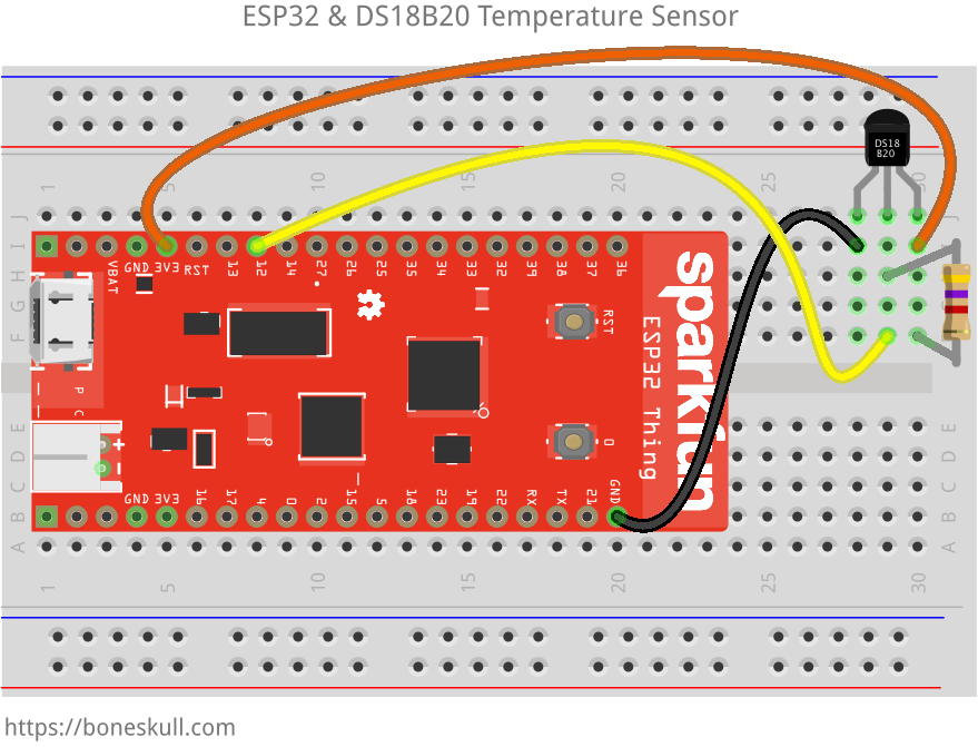
Example breadboard wiring for ESP32 dev board and DS18B20
To read temperature, we will create a Matryoshka-doll-like object by passing a Pin instance into a OneWire constructor (read about 1-Wire) and finally into a DS18X20 constructor:
pin = machine.Pin(12)
wire = onewire.OneWire(pin)
ds = ds18x20.DS18X20(wire)
Note that if the output of the following command is an empty list (
[]), the sensor couldn't be found. Check your wiring!
Now, we can ask ds to scan for connected devices, and return their addresses:
ds.scan()
Output:
[bytearray(b'(\xee3\x0c"\x15\x004')]
ds.scan() returns a list of device addresses in bytearray format. Yours may look slightly different. Since we only have one, we can save its address to a variable. To read temperature data, we tell the 1-Wire bus to reset via ds.convert_temp(), take a short pause of 750ms (in case you're pasting this):
import time
addr = ds.scan().pop()
ds.convert_temp()
time.sleep_ms(750)
temp = ds.read_temp(addr)
temp
Output:
19.875
This reading is in Celsius. If you’re like me, you don’t speak Celsius, so maybe you want to convert it to Fahrenheit:
(temp * 1.8) + 32
Output:
67.775
…which is right around what I expected!
Let’s take what we’ve done and create a new file, temperature.py:
import time
from machine import Pin
from onewire import OneWire
from ds18x20 import DS18X20


class TemperatureSensor:
    """
    Represents a Temperature sensor
    """
    def __init__(self, pin):
        """
        Finds address of single DS18B20 on bus specified by `pin`
        :param pin: 1-Wire bus pin
        :type pin: int
        """
        self.ds = DS18X20(OneWire(Pin(pin)))
        addrs = self.ds.scan()
        if not addrs:
            raise Exception('no DS18B20 found at bus on pin %d' % pin)
        # save what should be the only address found
        self.addr = addrs.pop()

    def read_temp(self, fahrenheit=True):
        """
        Reads temperature from a single DS18X20
        :param fahrenheit: Whether or not to return value in Fahrenheit
        :type fahrenheit: bool
        :return: Temperature
        :rtype: float
        """
        self.ds.convert_temp()
        time.sleep_ms(750)
        temp = self.ds.read_temp(self.addr)
        if fahrenheit:
            return self.c_to_f(temp)
        return temp

    @staticmethod
    def c_to_f(c):
        """
        Converts Celsius to Fahrenheit
        :param c: Temperature in Celsius
        :type c: float
        :return: Temperature in Fahrenheit
        :rtype: float
        """
        return (c * 1.8) + 32
Disconnect from the REPL. Upload temperature.py via ampy:
$ ampy -p /dev/tty.SLAB_USBtoUART put temperature.py
Then we can open our REPL once again, and try it:
from temperature import TemperatureSensor
t = TemperatureSensor(12)
t.read_temp() # use t.read_temp(False) to return Celsius
Seems to have warmed up a bit. Output:
68.7875
Good work!
Conclusion of Part One (1)
In the first part of this tutorial, we’ve learned how to:
- Flash an ESP32 dev board with MicroPython
- Use MicroPython’s REPL to experiment
- Connect the ESP32 to WiFi
- Upload and execute MicroPython scripts
- Read the temperature with a 1-Wire DS18B20 sensor
In the forthcoming second part of this tutorial, we’ll learn about MQTT, how to publish our temperature data to an MQTT broker, and likewise interface with an MQTT-based cloud “IoT platform”.